This page describes candidate Registers and features for the RealCoCo brand of CoCo 3 clones for the Matchbox, MiSTer, MiST, SiDi, and more FPGA devices.
Please check this document frequently for possible changes before releasing your software.
Because there are two types of FPGA systems we’re working with, OSD and non-OSD menus, some features are programmatic to the non-OSD while some features can be accessed by the OSD menu alone, and some can be accessed using either method.
These registers are not set in stone and are subject to change without notice, so please check back frequently if you’re developing software that uses extra “CoCo 4” features. Some of these features are planned and may not be implemented yet. I also accept recommendations via my Patreon page comments. Sign up and leave me your ideas.
Two types of GIME chip implementations are in consideration. Each should provide all regular CoCo 3 features, while either may have its own unique “CoCo 4” features. We’ll call these two advanced GIME chips “GIME-R” by Roger Taylor, and “GIME-X” by Ed Snider.
IRQENR (Interrupt Request enable/status) – $FF92 (65426)
- Bit 7 — Raster Interrupt (GIME-R)
- Bit 6 — GPU Interrupt (GIME-R)
- Bit 5 — GIME Timer
- Bit 4 — Horizontal Border
- Bit 3 — Vertical Border
- Bit 2 — Serial data
- Bit 1 — Keyboard
- Bit 0 — Cartridge
FIRQENR (Interrupt Request enable/status) – $FF93 (65427)
- Bit 7 — Raster Interrupt (GIME-R)
- Bit 6 — GPU Interrupt (GIME-R)
- Bit 5 — GIME Timer
- Bit 4 — Horizontal Border
- Bit 3 — Vertical Border
- Bit 2 — Serial data
- Bit 1 — Keyboard
- Bit 0 — Cartridge
(GIME-R) Extended Video Control Register – $FF10 (65296) read/write
- bit 7 — Allow video address to be changed mid-frame
- bit 6 — Double-width video (work in progress) requires twice as much video RAM
- bit 5 — Double-height video (x2 vertical resolution) requires twice as much video RAM
- bit 4 — Enable scanline effect
- bit 3 — Enable 256-color mode when CRES = 3
- bit 0 — Enable semi-graphics modes missing from the CoCo 3
(GIME-R) Rate Control Register – $FF11 (65297) read/write
- bit 7 —— Enable Throttle Mode (force CPU to run at a specific speed)
- bit 6 —— Enable Turbo Mode (skip CPU cycles when no memory is accessed)
- bits 5..3 — RAM rate: 00=.895 Mhz, 01=1.795 Mhz, 10=3.579 Mhz, 11=7.1509 Mhz
- bits 2..0 — Throttle rate: 00=.895 Mhz, 01=1.795 Mhz, 10=3.579 Mhz, 11=7.1509 Mhz
Try it from BASIC. POKE 65297,155 to overclock the CPU. Look at that cursor flicker! POKE 65297,0 to switch back to whatever the GIME/SAM says to do.
(GIME-R) System Control – $FF12 (65298) read/write
- bit 7 — Insert cartridge (hold the CART signal low)
(GIME-R) Raster Control $FF18..$FF19 (65304-65305) read/write (pending)
- $FF18 — (Write) Vertical count to interrupt (1-255, 0=All rows), (Read) Current vertical count
- $FF19 — (Write) Horizontal count to interrupt (0-255), (Read) Current horizontal count
Raster interrupts lets you know when the display is rendering a certain area of the screen. You can read the current coordinate whether the interrupt is enabled or not.
(GIME-R) Font Control – $FF1A (65306) read/write
- Bit 7 — Enable enhanced text attribute mode (xFFFFBBB)
- Bit 6 — Enable CP437 font with ‘PC’ graphics characters.
(GIME-R) Color Palette – $FFB0-$FFBF (65456-65471) read/write
16 slots of colors in the format defined by the Palette Control register.
(GIME-R) Palette Control – $FF1B (65307) read/write
- Bit 7 —— Enable 256-color DAC mode
- Bit 6 —–– Enable extended palette
-
Bits 5..4 –- Extended palette and DAC format
- 0 — xxRGBRGB (64 colors, Standard CoCo 3 format)
- 1 — xIRGBRGB (128 colors using intensity bit to CoCo 3 format)
- 2 — RGRGBRGB (256 colors)
- 3 — RRRGGGBB (256 colors)
- Bits 3..0 -– Palette Group 0-15
The Extended Palette switch combines several functions. All non 256-color modes can get their colors from one of 16 different palettes selected by the Palette Group Register. If this switch is off then the normal 16-color palette (group #0) will be displayed, otherwise the selected group will be used. This switch also enables writing more range bits into the palette slots using the selected format such as xIRGBRGB format where if I is the intensity of RGBRGB. In order to set up the 256-color palette, the normal CoCo 3 palette registers are used along with a group number. By enabling the Extended Palette and changing the Palette Group register, 16 different 16-color palettes can be configured. Furthermore, they can be switched very quickly making many special effects possible depending on when or where you change the palettes. Group 0 is the default when the Extended Palette isn’t enabled. The 256-color scheme of the Cyclone includes an 8-bit DAC mode where one byte is one pixel, and a palette mode where the video byte equals the palette slot. Because the CoCo 3 has only 16 palette registers, a Palette Group register has been added to the Cyclone to give a total of 16 standard GIME palettes totaling 256 color codes. So, 256 out of 512 colors can be shown at one time. Naturally the DAC mode and palette mode have their pros and cons depending on your software, game, or demo.
(Matchbox/DE0-Nano) ESP8266-01 WIFI Control Register – $FF1D (65309) read/write (Matchbox CoCo)
- Bit 7 — Enable RS-232 Pak DTR/DCD signals
- Bit 6 — Enable Direct Connect Modem Pak DTR/DCD signals
- bit 5 — 6551 overclocker (x4)
- Bit 3 — GPIO2
- Bit 2 — GPIO0
- Bit 1 — CHPDn
- Bit 0 — RESETn
(Matchbox/DE0-Nano) HC-05 Bluetooth – $FF1E (65310) read/write (Matchbox CoCo)
- bit 5 — 6551 overclocker (x4)
- Bit 2 — BT_EN, BT_KEY (write)
- Bit 0 — BT_STATE (read) – 1 indicates that you’re “On The Air.”
Some HC-05 modules might be configured slightly different than others. Some require the BT_EN pin to be held high during power-up in order to go into programming mode. Others need BT_EN to be held high during normal use for communications. To learn what the purpose of BT_EN is for your particular HC-05 style, please read the module instructions thoroughly. There are several ways to enable BT_EN: 1) hold down F12 on your keyboard to temporarily enable BT_EN or, 2) enable bit 2 of this register. You can observe the behavior of the HC-05 by toggling the BT_EN bit while connecting and disconnecting the CoCo from the paired remote device.
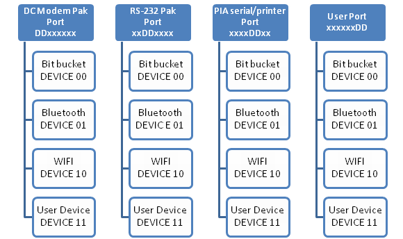
Telemux – $FF1F (65311) read/write
This register is awesome! It allows you to instantly rewire any of the 4 ports to any supported devices. Mix and match however you like but keep in mind that assigning the same device to two or more ports is a conflict and therefore a priority rule applies giving the duplicate device only to one port. It’s best to make sure each port has its own device.
- bits 7..6 — Device ## wired to the 6850 ACIA
- bits 5..4 — Device ## wired to the Deluxe RS-232 Pak port ($FF68)
- bits 3..2 — Device ## wired to the PIA serial/printer port
- bits 1..0 — Device ## wired to the User Port (user header pins 7,8)
Matchbox CoCo
- Device ’00’ = The ‘Bit Bucket’
- Device ’01’ = HC-05 bluetooth module, or any other module connected to the HC-05 header (Matchbox CoCo)
- Device ’10’ = ESP8266-01 WIFI module, or any other module connected to the 8266 header (Matchbox CoCo)
- Device ’11’ = User Device (user header pins 3,4)
IMPORTANT NOTES: On power-up of the Matchbox, the default is 10011100 (156) which means $FF6C = WIFI, $FF68 = HC-05, PIA Bitbanger = User Device, and User Port = Bit Bucket. The Matchbox DOS ROM ensures that $FF68 is remapped to the HC-05 module any time a CoCoNet drive is mounted or accessed. The CoCoNet drivers for OS-9 also use $FF68.
A special bluetooth/WIFI bridge directly connects the HC-05 module to the ESP8266-01 module such that all communications between the modules are done by the firmware on each module and/or the remote systems connected to the module(s). In other words, one module can act as a port into the other. One example of how this bridge can be used is the ability to reflash the WIFI firmware using the Bluetooth link. To activate the WIFI/Bluetooth bridge, don’t assign either device to a port. That is, no port should use device 01 or 10.
The following chart shows the ports (blue boxes) and their possible devices (white boxes).
Keyboard F-Keys
- F5 — Momentarily assert the HC-05 BT_EN/BT_KEY signal (Matchbox CoCo)
- F9 — Momentarily assert the CART signal (will run any mounted Program Pak)
Floppy Drive Controller (1793 and similar)
Currently on the Matchbox CoCo before it comes more up to date with the RealCoCo, the FDC looks at the size of a mounted disk to try to automatically determine how many “sides” and “tracks” it has, while the sectors per track is always 18. Headered virtual disks aren’t supported, nor is the ridiculous DriveWire disk format. As a rule of thumb, if the disk image size is not evenly divisible by 256, it’s probably not compatible. Additionally, if a disk is less than 161280 bytes (single-sided 35 track, standard format), it’s not compatible. If the disk size is larger than ~1.4MB (DS160 format), it’s assumed to be a single-sided “hard drive” or “mass drive” which requires the use of the SDC (SD card controller, Super Disk Controller, whatever you want to refer to it as), using LSN registers instead of track/sector/side. Currently on the RealCoCo if a disk is assumed to be incompatible by not following the rules above, it will be marked “Write Protected” so that you can attempt to run the contents while not being allowed to save anything to the disk. Disk formatting is currently not supported by the FDC, while the SDC formats by simply writing blank sectors by LSN # which works great with OS-9 using the “logical” option of the Format command.
SDC Data Register – $FF70 (65392) read/write
Once a Read/Write sector command has been issued, the SDC is waiting for 256 reads or 256 writes to the Data Register. Check the status register before each read or write so you don’t get ahead of the controller leading to missed data or corrupted sectors.
SDC Status Register – $FF71 (65393) read (Matchbox/RealCoCo as of 9/30/2021)
- Bit 7 — 1 = Sector byte ready is ready to read
- Bit 6 — Controller busy
- Bit 5 — Sector Transfer Busy
- Bit 4 — Valid FAT32 card (Matchbox CoCo3)
- Bit 3 — Disk image found/mounted
-
Bit 2 — SD card class
- 0 – SDSC
- 1 – SDHC
- Bit 1
- Bit 0 -– 1 = Write Busy
SDC Status Register – $FF71 (65393) read (proposed Matchbox/RealCoCo as of 10/1/2021)
- Bit 7 — Controller Busy, do not issue a command except for ‘Reset Controller’ if needed
- Bit 6 — LSN invalid, out of range, unavailable (check after writing to LSN registers)
- Bit 5 —
- Bit 4 —
- Bit 3 —
-
Bit 2 — Drive 1 has a disk mounted
- Bit 1 — Drive 0 has a disk mounted
- Bit 0 -– (1 = CPU can read a sector byte), (0 = CPU can write a sector byte)
SDC Command Register – $FF71 (65393) write
|
|
|
|
|
|
|
||
Virtual Disk Mounting Tips: Poke the command byte (32), wait a few CPU cycles, go into a loop until the Sector Busy signal goes High, then send the 11 characters for the 8.3 filename of the virtual disk. After sending each character you should wait until bit #0 of the Status Register goes Low. After the filename has been sent you should go into a timed loop until the Busy signal goes Low at which time you can check the Disk Image Found bit to determine whether your image was mounted or not.
Direct mode and Image mode are Per Drive commands that tell the controller to access the card directly starting at LSN 0 or the currently-mounted virtual disk. Mounting an image will put the specified drive into Image Mode automatically. Switching to Direct Mode does not dismount any images. Therefore, you can switch between Direct and Image.
Get Mount Name: Write the command byte then read the data port 11 times to get the 8.3 filename for the mounted image on the specified drive #.
SDC LSN Register – $FF72-$FF75 (65394-65397)
| $FF72 LSN bits 23..16 |
$FF73 LSN bits 15..8 |
$FF74 LSN bits 7..0 |
$FF75 LSN bits 31..24 Read-only |
This is a dual-purpose register! The CoCo is limited to 24-bit LSNs in SDC mode, and up to 256 tracks * 18 sectors in FDC mode. This range is within the mounted image being accessed which could reside anywhere on a 32-bit SD card. To find out where your image is located on the card, mount the image then do a read of LSN $000000 if SDC mode, or track #0, sector #1 if FDC mode, then read all 4 of the SDC LSN registers back to see the actual SD location of the image (Pending feature).
(Matchbox/DE0-Nano) Disk Drive Mounting
For better compatibility with DOS and OS-9, the floppy drive controller circuit is tied to the SD card interface internally. All that’s really needed by DOS and OS-9 is to mount a virtual floppy disk in the FDC. This basically points to the top of the disk image on the SD card and then the FDC accesses the card instead of a real floppy disk.
To set up an SD card for use with the Cyclone, format the card as “FAT32” from Windows or Linux or any other device that can format an SD card. The card is now ready to hold thousands of floppy and hard drive image files that will work like the real drives on the Cyclone.
To boot into an OS-9 “disk” named “OS9.DSK” on the SD card:
- DOS “OS9” or
- DRIVE 0,”OS9″:DOS
To mount Sock Master’s demo disk and do a listing then run one of the demos:
- DRIVE 0,”SOCK”
- DIR
- LOADM “BOINK”
- EXEC
To mount a virtual disk over the CoCoNet system (requires the CoCoNet server on the remote system):
- DRIVE 0,@”SOCK”
- DIR
- LOADM “BOINK”
- EXEC
AY-3-891x/YM2149 Sound Controller – $FF96-$FF97 (65430-65431)
- $FF96 — Address and Data
-
$FF97 — Control
- Bits 7..2 — undefined
- Bit 1 —— BC1
- Bit 0 —— BDIR
BC2 is always wired High and requires no setting. Although the Tandy Sound/Speech Pak uses this chip for the music, the pak isn’t supported yet.
Orchestra-90CC – $FF7A-$FF7B (65402-65403)
- $FF7A — 8-bit left channel DAC
- $FF7B — 8-bit right channel DAC
The Orchestra-90CC circuitry attempts to duplicate the RCA jack outputs of the original cartridge. These outputs can be fed into a stereo amplifier and sound can be heard no matter what other sound or analog devices are being used by the CoCo. Therefore, if anything is POKED to these registers, the sound heard by the Cyclone CoCo will include these DAC outputs.
Proposed, Work In Progress
Direct Mouse/Joystick Coordinates – $FF14..$FF17 (65300-65303) read
- $FF14 — Horizontal coordinate, bits 15..8
- $FF15 — Horizontal coordinate, bits 7..0
- $FF16 — Vertical coordinate, bits 15..8
- $FF17 — Vertical coordinate, bits 7..0
You want the mouse or joystick to work in any game or software, hi-res or lo-res mode, automatically. No problem! Besides the convenience of reading the tracker coordinates directly, the regular 6-bit ADC and various hi-res adapters are automatically supported and utilized no matter if you’re using a PS/2 mouse or real CoCo joysticks or CoCo mouse.
GPU (Graphics Processing Unit) – $FF30-$FF34 (65328-65332) (pending)
Prepare to be impressed with a new and extremely fast way of performing certain graphics and memory functions. How does it work? Enter DMA. A graphics processor core has been added that runs all the time in the background and can access the regular CoCo RAM whenever the CPU isn’t using it which is about 20% of the time when the CPU isn’t HALTed, or 100% of the time when the CPU is HALTed. In no-HALT mode all of the commands are completely transparent to the system and take up no extra time to perform. There is also an interrupt signal sent to the GIME whenever a command is complete, meaning you can cycle through a list of commands using the CoCo’s IRQ/FIRQ system and perform complex and lengthy operations that seem to be completely transparent to the CoCo.
The GPU only deals with bytes and therefore works best with the 256-color mode. If the Width or Height is Zero then operation is performed on contiguous memory of size (Width + Height), otherwise a rectangle area. If the Width and Height is Zero then operation is performed for a single source byte to a single destination byte.
Another awesome feature of the GPU is that it bypasses the CoCo 3’s MMU system and lets you specify the actual RAM addresses involved using the 24-bit Source and Destination registers.
IMPORTANT: When writing to the 24-bit GPU registers, a separate CPU instruction is required for each register BYTE. That is, a 16-bit value store to 2 of the register bytes at once is not supported at this time due to the nature of the GPU. Instead, do something like LDD #WIDTH, CLR REG+0, STA REG+1, STB REG+2.
-
$FF30 – Command register (write)
- Bit 7 —— HALT CPU during command
- Bit 6 —— Use transparency
- Bits 4..0 – Command
-
$FF30 – Status register (read)
- Bit 7 – Command is done
- Bit 0 – GPU is busy
- $FF31 – Register number (write)
-
$FF32..$FF34 – Register contents (write)
- $FF32 – bits 23..16
- $FF33 – bits 15..8
- $FF34 – bits 7..0
| GPU Commands | |
| Working |
Pending |
| 00001 – Fill (fill a contiguous area of RAM or a rectangle area using BPR and DEST. If width or height is 0 then fill contiguous memory) | 00000 – Null (Good for checking status of GPU or kick-starting an interrupt-driven sequence.) |
| 00010 – Copy (copy SOURCE to DEST with limited logic such as NOT and XOR) | 00101 – Circle |
| 00011 – Mix (logical mix SOURCE with SOURCE2 with results going to DEST) | 00111 – Flood |
| 00100 – Line (uses DESTVECT, should normally have SOURCEVECT set to 0,0) | |
| 01000 – Move (uses SOURCEVECT) | |
| 00101 – Circle | |
| 00110 – Goto (uses SOURCE) | |
| GPU Registers * = pending |
|
0 – LOGIC
x001 = OR |
|
| 1 – COLOR | |
| 2 – TRANSPARENT | |
| 3 – RESOLUTION (pending) | |
| 4 – WIDTH (fill, copy, mix) | |
| 5 – HEIGHT (fill, copy, mix) | |
| 6 – SOURCEVECT X (start vector for line, etc.) | |
| 7 – SOURCEVECT Y | |
| 8 – DESTVECT X (end vector for line, etc.) | |
| 9 – DESTVECT Y | |
| 10 – RADIUS (pending use for circle) | |
| 16 – SOURCE (starting address) | |
| 17 – BPR (bytes per row for fill, copy, mix source) | |
| 32 – SOURCE2 (address for mix) | |
| 33 – BPR2 (bytes per row for mix) | |
| 48 – DEST (destination address for copy, mix) | |
| 49 – DESTBPR (bytes per row for copy, mix) | |
Matchbox CoCo (DE0-Nano FPGA with NanoMate I/O board)
| NanoMate GPIO1 | Cyclone IV Pin | NanoMate GPIO1 | Cyclone IV Pin | |
| IR Data In | T9 | SD CS | F13 | |
| User IN-C | R9 | SD MOSI | T15 | |
| WIFI IO1 | T14 | SD CLK | T13 | |
| WIFI Reset | R13 | SD MISO | T12 | |
| WIFI Receive | R12 | DAC LDAC | T11 | |
| VCC5 | GND | |||
| WIFI Transmit | T10 | BT TX | R11 | |
| WIFI CHPD | P11 | BT RX | R10 | |
| VGA Blue 2 | N12 | BT KEY | P9 | |
| VGA Green 2 | N9 | BT STATE | N11 | |
| VGA Red 2 | L16 | DAC SCK | K16 | |
| VGA Blue 1 | R16 | DAC SDI | L15 | |
| VGA Green 1 | P15 | DAC CSN | P16 | |
| VGA Red 1 | R14 | SRAM CE2n | N16 | |
| VCC33 | GND | |||
| VGA Blue 0 | N15 | WIFI IO0 | P14 | |
| VGA Green 0 | L14 | KEY CLK | N14 | |
| VGA Red 0 | M10 | KEY DATA | L13 | |
| VGA HSYNC | J16 | MOUSE DATA | K15 | |
| VGA VSYNC | J13 | MOUSE CLK | J14 |
| NanoMate GPIO0 | Cyclone IV Pin | NanoMate GPIO0 | Cyclone IV Pin | |
| User IN-B | A8 | IO3 | D3 | |
| User IN-A | B8 | IO2 | C3 | |
| SRAM A15 | A2 | IO1 | A3 | |
| SRAM A17 | B3 | FRONT LED | B4 | |
| SRAM A18 | A4 | SRAM A16 | B5 | |
| VCC5 | GND | |||
| SRAM A14 | A5 | SRAM WEn | D5 | |
| SRAM A12 | B6 | SRAM A13 | A6 | |
| SRAM A7 | B7 | SRAM A8 | D6 | |
| SRAM A6 | A7 | SRAM A9 | C6 | |
| SRAM A5 | C8 | SRAM A11 | E6 | |
| SRAM A4 | E7 | SRAM OEn | D8 | |
| SRAM A3 | E8 | SRAM A10 | F8 | |
| SRAM A2 | F9 | SRAM CE1n | E9 | |
| VCC33 | GND | |||
| SRAM A1 | C9 | SRAM D7 | D9 | |
| SRAM A0 | E11 | SRAM D6 | E10 | |
| SRAM D0 | C11 | SRAM D5 | B11 | |
| SRAM D1 | A12 | SRAM D4 | D11 | |
| SRAM D2 | D12 | SRAM D3 | B12 |
