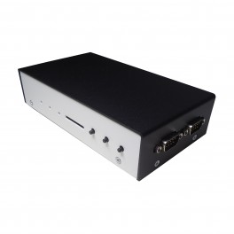
For the Matchbox CoCo, the CoCo’s logic completely resides on the DE0-Nano board. Realistically jumpers can be strung from the DE0-Nano headers to give the system the things it needs to be complete, but ideally you’d want some of that to be very close to the main board, and for the sake of compactness alone a consolidated solution is the best choice for making a snap-together CoCo clone. In fact, without the NanoMate board we might be hard pressed to rename this CoCo clone to something more reflective of an octopus or tarantula.
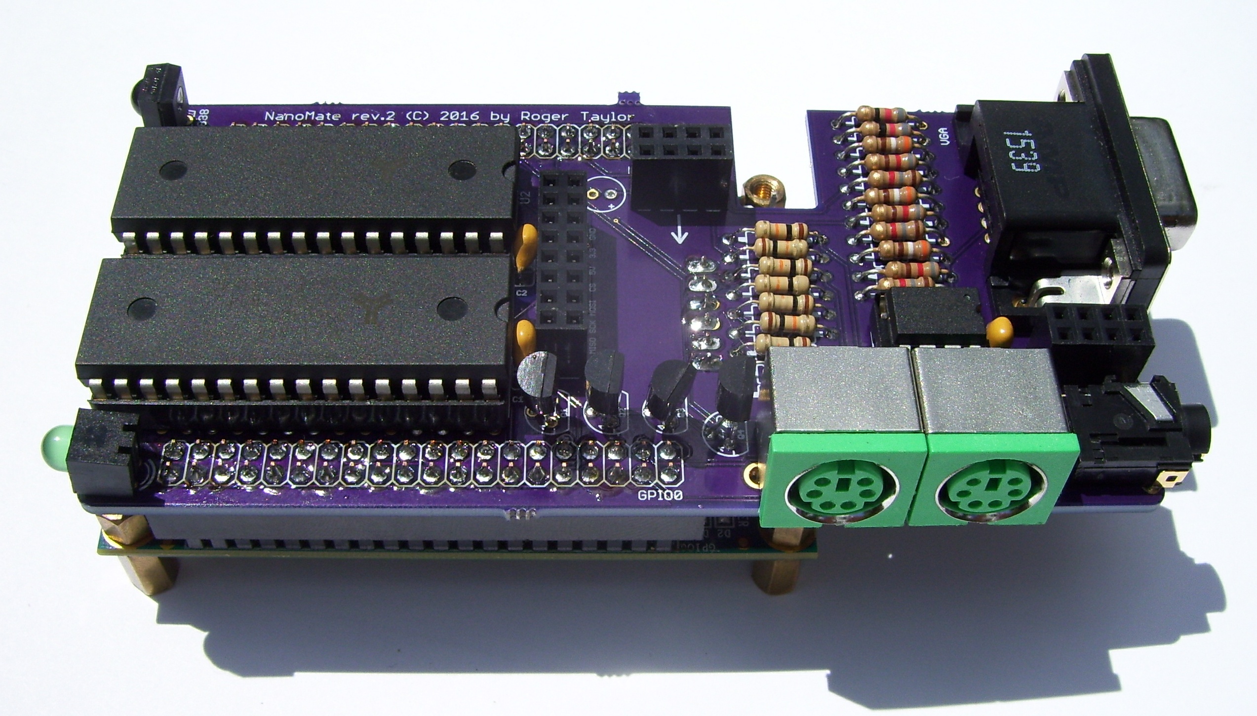
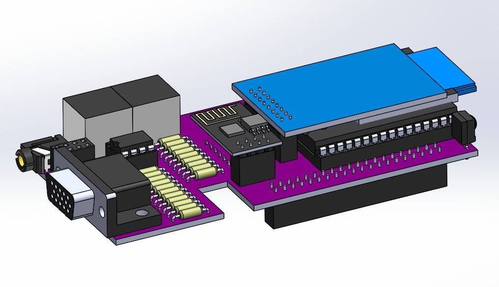
The NanoMate daughter board is a custom circuit board designed to plug on top of the DE0-Nano to give the extra hardware needed for the full CoCo design, including VGA, 1MB RAM, PS/2 keyboard and mouse, stereo audio, SD card drives, WIFI, Bluetooth serial, and a user I/O header accessible from BASIC or machine language.
This 4-layer board can be ordered from the OSH Park web site for about $88 for 3 boards. The components to fully assemble the board cost around $40 with most parts being available from Digi-Key.
 Summary of features:
- 1MB SRAM
- 3-bit VGA (3 bits per component, or 512 possible colors)
- SD card slot
- MCP4822 stereo audio DAC and 1/8″ audio jack
- Female VGA port
- PS/2 keyboard
- PS/2 mouse
- 2×4 User I/O header
- ESP8266-01 WIFI module header
- HC-05 bluetooth module header underneath the board
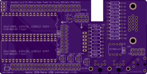
Buy 3 bare NanoMate daughter boards from OSH Park
DIGI-KEY Preloaded Shopping Carts for the components that go on a bare NanoMate board. Take note that often Digi-Key will discontinue a certain part # while picking up other part #’s for what’s essentially the same exact part, so please study your shopping cart to see if all of the required items were added, and if not manually find them on the site and add them to your cart.
- I live in the USA and I need to assemble 1 NanoMate board.
- I live in the USA and I need to assemble 1 NanoMate board, and throw in *1* Terasic DE0-Nano.
- I live in the USA and I need to assemble 3 NanoMate boards.
- I live in the USA and I need to assemble 3 NanoMate boards, and throw in *3* DE0-Nanos.
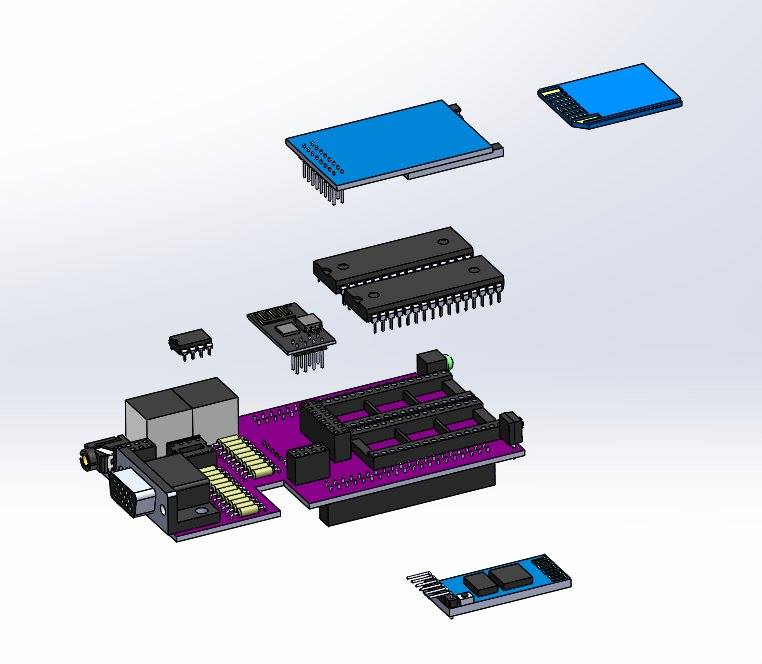
Optional modules that plug into the NanoMate:
- LC-Tech / LC Studios SD card interface or any SD interface that has the same pin arrangement as the SD header. See board labeling for pin names.
- HC-05 bluetooth serial module, underneath the board, runs parallel flush to the board surface.
- ESP8266-01 WIFI module, observe the orientation arrow next to header.
Please note that you’ll need to compare your FINAL ORDER with the Bill Of Materials below to determine what REMAINING parts you need to buy from places like Amazon, Ebay, Jameco, or another electronics supplier.
Why would you need the parts for *3* systems?? Because the NanoMate PCB supplier (OSH Park) only sells in multiples of 3 boards, and it is cost effective to do the same for the components and either send kits or fully assembled units to other people.
(2) – 2×20 straight male header (is keyed) for connecting NanoMate to DE0-Nano (Digi-Key S9200-ND)
(3) – 390 ohm, 5%, VGA lower bits
(3) – 820 ohm, 5%, VGA middle bits
(1) – 820 ohm or near for 3.3V front panel green LED
(3) – 1.8K ohm, 5%, VGA upper bits
(2) – 82 ohm – VGA HSYNC, VGA VSYNC
(8) – 10K ohm – for PS/2 bi-directional level shifters
(4) – 2N7000 transistor, for PS/2 bi-directional level shifters (Digi-Key 2N7000TACT-ND)
(3) – 0.1uF decoupling capacitors for SRAM and MCP4822 DAC
(1) – 2×4 straight male header for ESP8266-01 Wifi module (Digi-Key S7107-ND)
(1) – 1×6 right-angle male header for HC-05 or HC-06 bluetooth module (Digi-Key S5481-ND)
(1) – 2×8 straight male header for SD card module (Digi-Key S7076-ND)
(2) – AS6C4008-55PCN 512KB SRAM (Digi-Key 1450-1027-ND)
(2) – 32-pin sockets for SRAM (highly recommended!) (Digi-Key ED3053-5-ND)
(1) – VGA jack (Digi-Key A35116-ND)
(1) – audio jack (Digi-Key CP-43514-ND)
(2) – PS/2 jacks (Digi-Key CP-4060-ND) (Amazon, ebay, Amazon) (Has common/popular pinout; some connectors may need their anchors straightened using pliers due to the very tight fit on some NanoMate boards. However, the snug fixture will reduce or eliminate issues resulting from plugging in PS/2 devices frequently.)
(1) – 5mm 3.3v green LED for front panel (Digi-Key 350-1598-ND)
(1) – MCP4822 stereo audio DAC (12-bit), but 4812 and 4802 will also work. (Digi-Key MCP4822-E/P-ND)
(1) – 8-pin socket for audio DAC (Digi-Key AE9986-ND
(1) – SD card module ($2.84 USA Ebay Seller, free shipping)
(1) – TSOP4838 infrared receiver (Digi-Key TSOP4838-ND)
(1) – ESP8266-01 WIFI Module (Amazon USA Seller, Amazon, ebay)
(1) – 47 uF decoupling capacitor for WIFI module (Digi-Key P5137-ND)
(1) – optional HC-05 bluetooth module (Amazon)
(1) – 2/4/8GB SD/SDHC memory card formatted as FAT32.
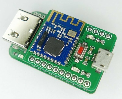
Programming the ESP-01 / ESP8266-01
This can be done from the NetMate software that runs on a CoCo 3 or the Matchbox, although it’s a little learning curve. The Matchbox CoCo with NetMate knows how to internally couple the ESP8266 to the HC-06 Bluetooth module so that you can flash the ESP8266 from the Arduino IDE. Typically we’d want the Telnet Modem firmware to run on the ESP8266, but you can probably do MQTT stuff and other custom firmware. Here’s a nice little USB programmer for the ESP8266. I wish I had this back when I was developing the Matchbox CoCo and Nanomate daughter board.
ESP8266 Programmer Dongle
Assembly Guide
Most components are either obvious or marked with the part # on the board. The only difference in the rev.3 and rev.4 board is the rotation of the WIFI module header.
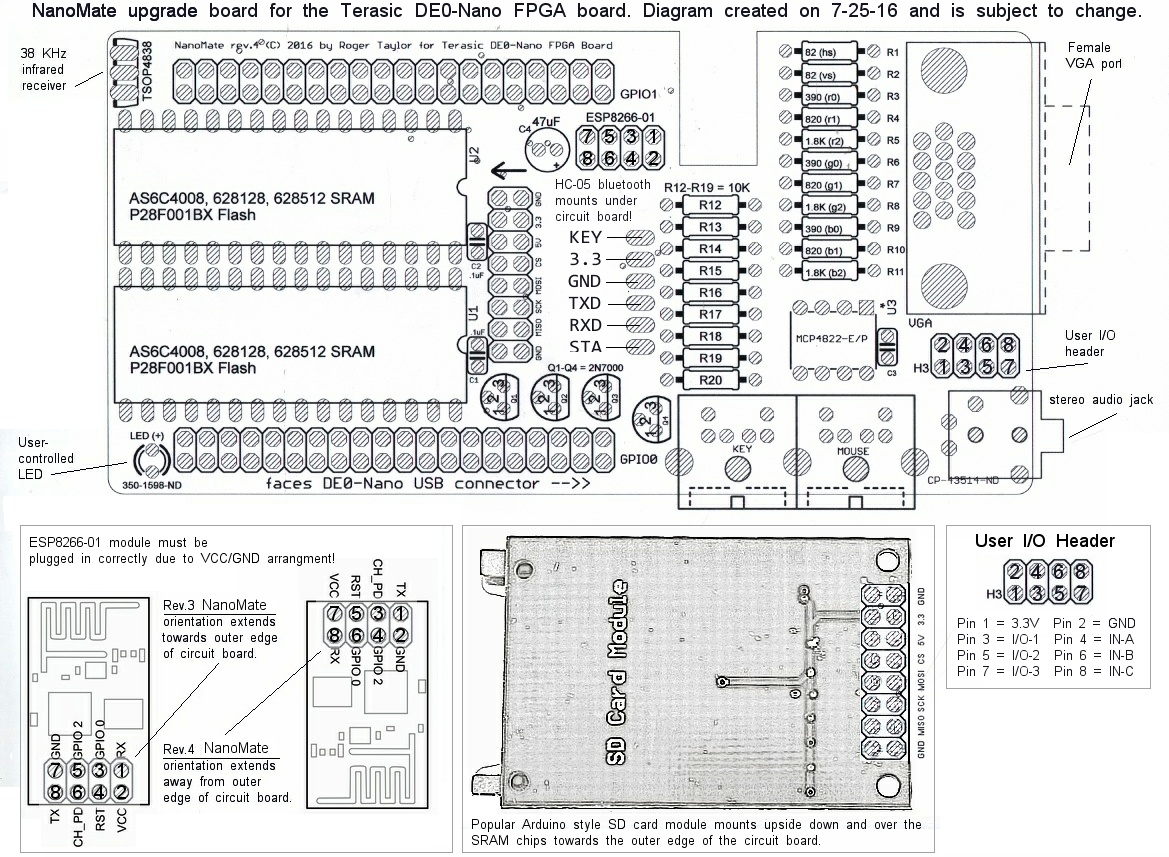 For the rev.3 board, the WIFI module must extend away from the board. For the rev.4 board, the WIFI module faces in the direction of the arrow next to the header.
- R1 ……….. 82 Ohm resistor for VGA HSYNC
- R2 ……….. 82 Ohm resistor for VGA VSYNC
- R3,R6,R9 ….. 390 Ohm resistor for VGA Red0,Green0,Blue0
- R4,R7,R10 …. 820 Ohm resistor for VGA Red1,Green1,Blue1
- R5,R8,R11 …. 1.8K Ohm resistor for VGA Red2,Green2,Blue2
- R12-R19 …… 10 KOhm resistor for PS/2 level conversion
- R20 ………. ~150 Ohm (bright) to ~820 Ohm (dimmer) resistor for front panel LED
- C1,C2,C3 ….. .1 uF (104) ceramic capacitor for decoupling
- C4 ……….. 47 uF 25V electrolytic capacitors for WIFI module decouple
- Q1-Q4 …….. 2N7000 N-channel MOFSET transistor for PS/2 level conversion.
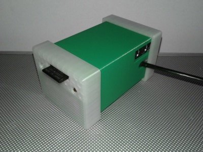
You MUST REMOVE the DE0-Nano’s top plastic dust cover and 4 SCREWS before installing the NanoMate daughter board!
Keep the screws which will be used to fasten the whole system including the Nanolog board to the bottom of the plastic case.
| NanoMate GPIO1 | Cyclone IV Pin | NanoMate GPIO1 | Cyclone IV Pin | |
| IR Data In | T9 | SD CS | F13 | |
| User IN-C | R9 | SD MOSI | T15 | |
| WIFI IO1 | T14 | SD CLK | T13 | |
| WIFI Reset | R13 | SD MISO | T12 | |
| WIFI Receive | R12 | DAC LDAC | T11 | |
| VCC5 | GND | |||
| WIFI Transmit | T10 | BT TX | R11 | |
| WIFI CHPD | P11 | BT RX | R10 | |
| VGA Blue 2 | N12 | BT KEY | P9 | |
| VGA Green 2 | N9 | BT STATE | N11 | |
| VGA Red 2 | L16 | DAC SCK | K16 | |
| VGA Blue 1 | R16 | DAC SDI | L15 | |
| VGA Green 1 | P15 | DAC CSN | P16 | |
| VGA Red 1 | R14 | SRAM CE2n | N16 | |
| VCC33 | GND | |||
| VGA Blue 0 | N15 | WIFI IO0 | P14 | |
| VGA Green 0 | L14 | KEY CLK | N14 | |
| VGA Red 0 | M10 | KEY DATA | L13 | |
| VGA HSYNC | J16 | MOUSE DATA | K15 | |
| VGA VSYNC | J13 | MOUSE CLK | J14 |
| NanoMate GPIO0 | Cyclone IV Pin | NanoMate GPIO0 | Cyclone IV Pin | |
| User IN-B | A8 | IO3 | D3 | |
| User IN-A | B8 | IO2 | C3 | |
| SRAM A15 | A2 | IO1 | A3 | |
| SRAM A17 | B3 | FRONT LED | B4 | |
| SRAM A18 | A4 | SRAM A16 | B5 | |
| VCC5 | GND | |||
| SRAM A14 | A5 | SRAM WEn | D5 | |
| SRAM A12 | B6 | SRAM A13 | A6 | |
| SRAM A7 | B7 | SRAM A8 | D6 | |
| SRAM A6 | A7 | SRAM A9 | C6 | |
| SRAM A5 | C8 | SRAM A11 | E6 | |
| SRAM A4 | E7 | SRAM OEn | D8 | |
| SRAM A3 | E8 | SRAM A10 | F8 | |
| SRAM A2 | F9 | SRAM CE1n | E9 | |
| VCC33 | GND | |||
| SRAM A1 | C9 | SRAM D7 | D9 | |
| SRAM A0 | E11 | SRAM D6 | E10 | |
| SRAM D0 | C11 | SRAM D5 | B11 | |
| SRAM D1 | A12 | SRAM D4 | D11 | |
| SRAM D2 | D12 | SRAM D3 | B12 |