An illustrated review of Luis Antoniosi’s RGB2VGA converter
This is a personal review of the RGB2VGA video converter designed by Luis Antoniosi.
First, let me say that it is high time that the CoCo community get some real quality video and experience the CoCo in a new way. Numerous people have attempted to make various video converters for the CoCo, but some have fallen way short on expectations, while some have done a good job and deserve much credit. While everybody deserves credit for making the CoCo work with modern devices, nobody has really designed a near pixel-perfect converter… UNTIL NOW.
After you review this page and learn what’s required to get a converter built, be sure to visit Zippster’s site for his version of the converter complete with updated resistor values and other tips that you MUST know in order to have the best quality.
As this page is being updated, I’ll add more details about how I followed this project from the time of noticing Luis’ web page to several weeks later when I jumped out of my chair and started laughing with shock when the nuclear green CoCo screen appeared for the first time on my VGA monitor.
Thank you, LUIS ANTONIOSI for your hard work and continued efforts with this project. We’ll be watching you for new stuff!
For now, I’ll talk a little about the pictures on this page. Click on a picture to see a larger version, and follow with me through a day or two of giving my CoCo another long lease on its life.
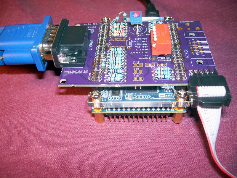
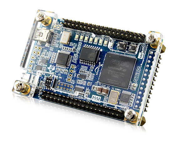 Terasic DE0-Nano FPGA board |
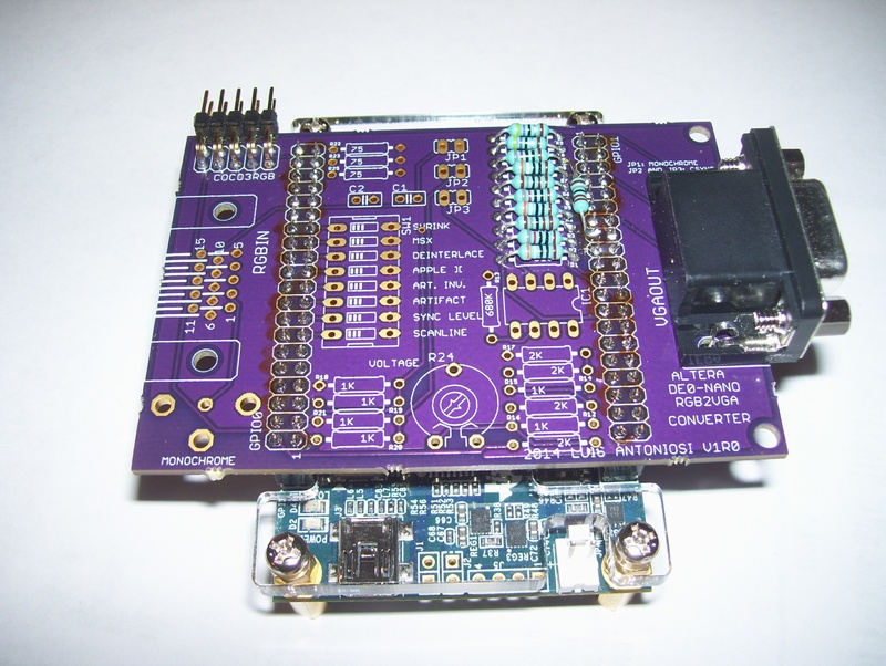
The RGB2VGA 1.0 converter REQUIRES the Altera DE0-Nano FPGA module. The RGB2VGA is a daughter board for the DE0-Nano. Together they work to form a 100% hardware gadget that does the CoCo 3 – to – VGA conversion in real time. The price for a new Nano can range from about $79 to $99 (give or take $20). It comes with a USB cable and Quartus II software for fully programming the device. Yes, YOU can do it from your PC. You’ll have to program the FPGA with Luis’ DE0-Nano code which you can find on his web site mentioned above. More details about setting up the Nano or updating its code will be added on this page soon. Basically once you set it up right, it will power up and start converting right away. No further configuration is needed. The price is worth it once you see the quality and upgrade possibilities for VGA video on your CoCo 3. | |
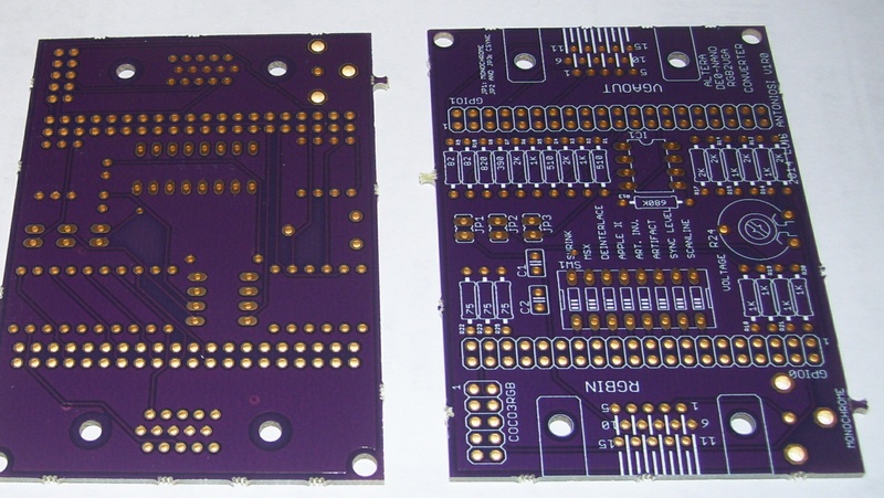 |
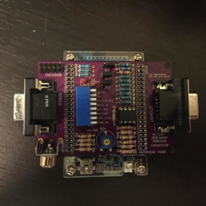
Top/bottom of the RGB2VGA board. Don’t let all the required parts scare you. Not all parts are required for CoCo operation, which you can decide on your own after studying the schematics. For example, the 15-pin RGB In jack, the Monochrome Out jack, the SYNC separator chip, and several resistors and caps, aren’t required to make this converter work for the CoCo 3.
You can order 3+ boards from here. |
|
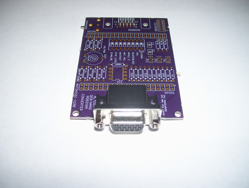 |
This picture shows the VGA Out jack soldered in place. It’s a PCB-mount female jack since most VGA monitors have a male cable. A U.S. seller on Amazon has 4 for about $8.81 which includes postage. The mounted jack is very stable and is held in place very well. From my experience — “it ain’t going anywhere”. | |
 |
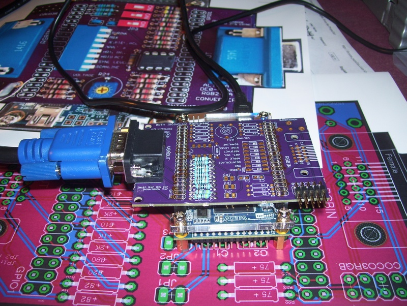
The 10-pin header for the CoCo RGB cable can be a straight version or 90-degree version. It’s up to your preferences and space restrictions.
By the way, you’ll need a 10-pin female-to-female header ribbon cable or any other type of cable with two 10-pin female headers on either end that’s long enough to reach from the bottom of the CoCo motherboard to your converter unit. My cable is about 3 feet long because I just happen to find one in my junk boxes. If your unit is going to be inside of your CoCo case (will it even fit?) obviously you can get by with a much shorter cable.
|
|
 |
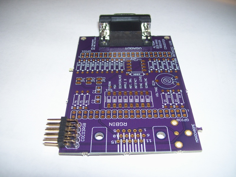
The female headers that connect this board to the DE0-Nano are two 40-pin sockets, each having 2 rows of 20 pins. I used four 2×10 headers and they worked just fine by butting them together. Look close in the picture for the seam.
TIP: slide the female headers onto the DE0-Nano’s male GPIO headers BEFORE soldering! Set the RGB2VGA board onto the soldering pins of the headers and start soldering, starting with the corner pins on each header while pushing down slightly, then relax because you have a lot of pins to go!. Doing this will result in the best alignment of the daughter board to the Nano. Actually, the RGB2VGA and Nano are aligned very nicely but it’s the HEADERS that you don’t want to make a mistake with. |
|
 |
This is a ‘minimum components’ test that got me a basic “VGA port” for the DE0-Nano. In other words, the Nano can be programmed with any VGA code that knows how to output on the right GPIO pins of the RGB2VGA board. There are 9 resistors for the color signals and 2 resistors for the video SYNC signals. The CoCo cable header doesn’t have to be there if you’re going to use the RGB2VGA board for only outputting VGA with other projects, but let’s not get side-tracked… we have to get video for your CoCo 3, so keep the soldering iron hot. | |
 |
This photo shows a partial assembly hooked to the Nano and the VGA monitor, ready to show Luis’ color chart that appears when no CoCo video is detected. Thankfuly, during assembly you can actually stop your soldering and plug the Nano in and see the video quality improving as you add the DAC resistors, etc.
Notice how I put my color laser printer to work for this project, too. I printed out enlarged versions of the pictures shown on Luis’ web site so I could make sure the assembly goes smoother. His close-up photos showing resistor color bands is a good reference while you’re soldering. In fact, the laser printout was so detailed that the resistors actually looked like they were mounted on the paper! |
|
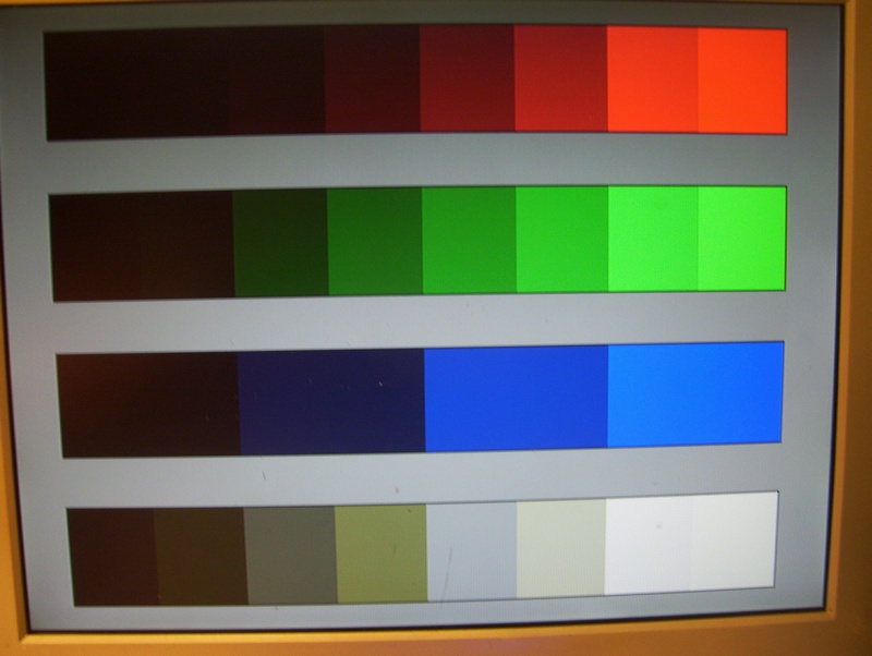 |
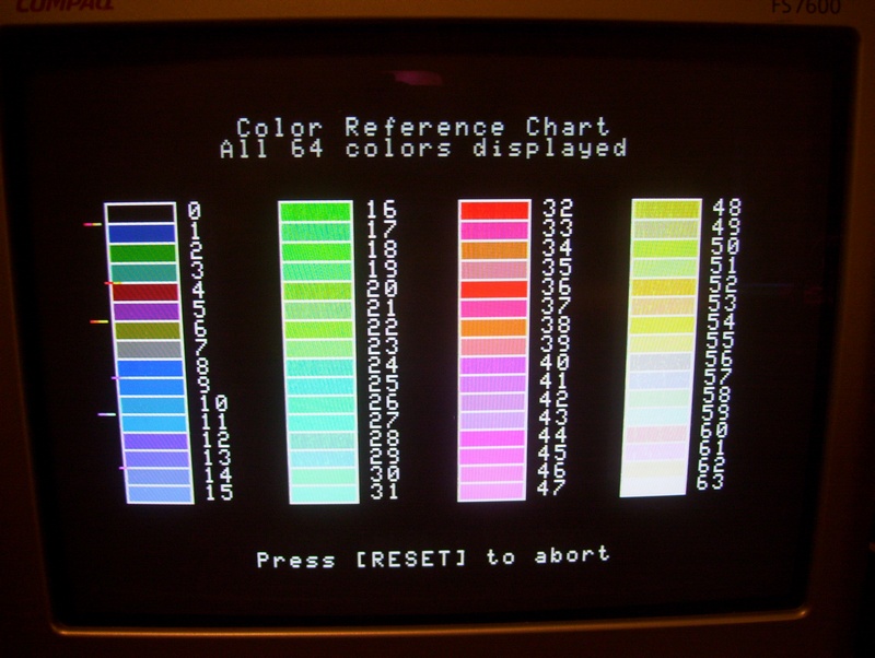
You’ll know you haven’t finished if you see this chart. Luis originally designed an 8-bit converter with a 3-3-2 RGB DAC, but later added the third blue bit giving us 3-3-3 for 9 bits of precision.
So, if you see this chart, you’re looking at 3-3-2 precision and have yet another resistor to solder. It’s not an easy one to squeeze in, but if you’ve made it this far you can do it. See Luis’ web site for the details!
|
|
 |
The “third blue bit” resistor is soldered in place, and voila — full color!
8 levels of red 8x8x8 = a RANGE of 512 colors for OUTPUT. This is jut a test pattern showing the output capabilities of the RGB2VGA. Now we have to get the converter to SEE the CoCo’s video signal correctly so the overall conversion works as it should. |
|
 |
Again, if you made it past the 3rd blue bit resistor, you’re not out of the woods just yet.
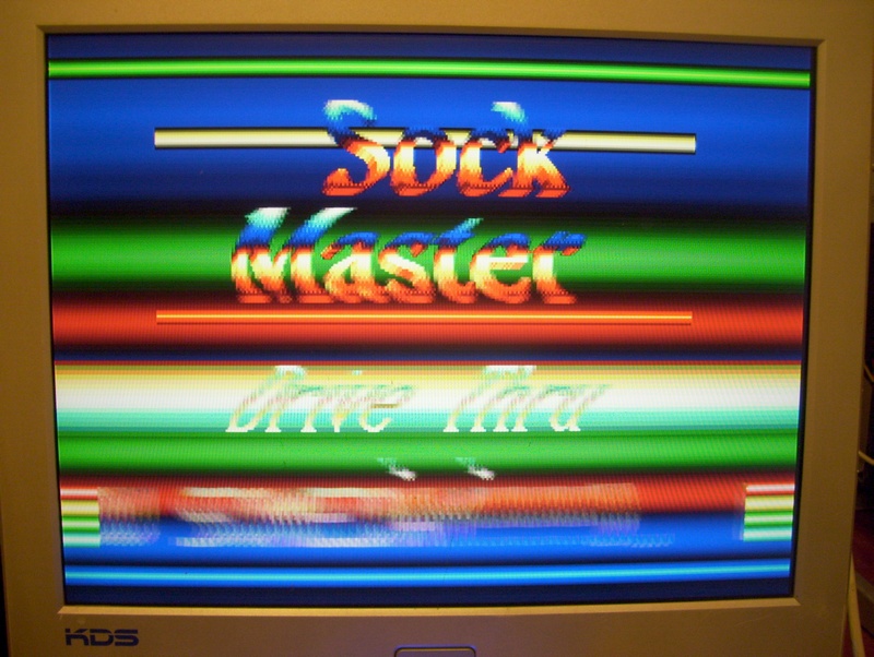
If you don’t have the trimmer (R24) soldered in yet, the converter will not “see” the CoCo’s RGB output accurately and you’ll get video that looks something like the picture here. You must use a multi-turn precision 10k trimmer or you’ll find that it’s quite hard to tune the colors. |
|
 |
Now that you’ve soldered the trimmer in place and powered the unit back up, you notice that the missing colors appear and some of the colors have changed a little, but all the colors are here!
But wait, what’s that noise going on in some of the colors? Some of the colors in the 2nd and 4th column are wavy and jittery, and some colors look the same. Actually, this is normal because the variable resistor hasn’t been adjusted yet. To make a long story short, the RGB2VGA’s trimmer is used to fine-tune the circuit like how most video equipment is tuned on their circuit boards. With most resistors being not exact, and with a circuit like this requiring that the ADC be perfect, and with no two CoCo 3’s outputting the same exact quality of video signal, and with even the smallest of timing differences possible, all small issues combined can throw the harmony off, but the trimmer is used to tweak the balance. Once set you shouldn’t have to keep readjusting it. |
|
|
|
A slow turn of the variable resistor and FINALLY, a stable set of colors. Now is also a good time to set the brightness and contrast on your monitor either manually or using any auto-adjustment features.
I’d have to compare this chart carefully with one from other users or to my CM-8 monitor, but it sure looks good to me for only 3 bits of color resolution! Now, it’s time to fire up some demos and games!
|
|
 |
Look at this! The ball is virtually jumping off the screen! Notice the range of checkerboard colors are Pretty Darn Accurate!
A video of this demo on an old RGB monitor can be see on youtube in case you’re wondering if Sockmaster is actually able to make that ball jump off your screen. Don’t doubt him! 🙂 At this point you can relax and know that the converter WORKS GREAT, so please take the time to thank Luis Antoniosi for his hard work and efforts in designing all of this! |
|
 |
No, your converter didn’t just go haywire! That’s just Sockmaster “messing with the palettes” as usual. A video of this demo can be see on youtube in case you’re wondering what’s going on with this picture. If your monitor or device doesn’t catch on fire when this demo runs, you’re gonna be Just Fine! 🙂 | |
 |
 |
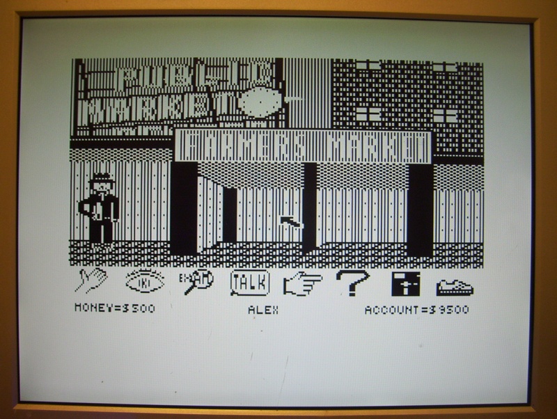
One option on the DIP switch is the “Artifact” mode. As always, it’s bad for text, good for graphics. Here is a comparison of The Interbank Incident which was one of many CoCo games that were designed to take advantage of the artifacting effect of some graphics modes. For this particular game, you’d want Artifact mode to be on, but good luck reading some of the text, as the RGB2VGA unit exaggerates it a tad, in my opinion. I think if the effect was cut in half that it would yield a better mix between fake color and readable text. |
 |
 |
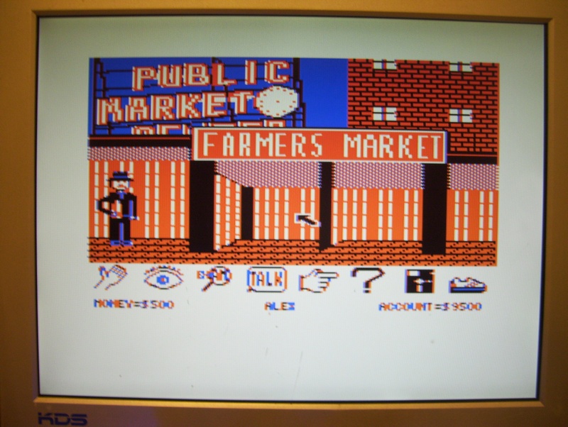
Here’s another game where the monochrome version is terrible, as with most games that intentionally produce artifact colors. However, notice how the text is always nice and crisp when Artifact mode is off. In fact, the RGB2VGA simulates the No Color Burst mode of the CoCo 3 which completely kills the possibility of any fake colors being introduced in the video. |
 |
 |
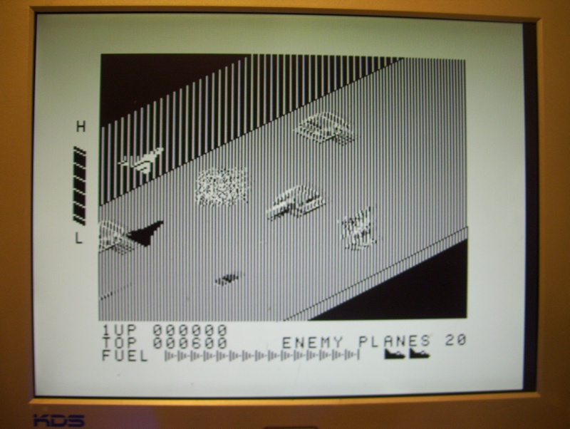
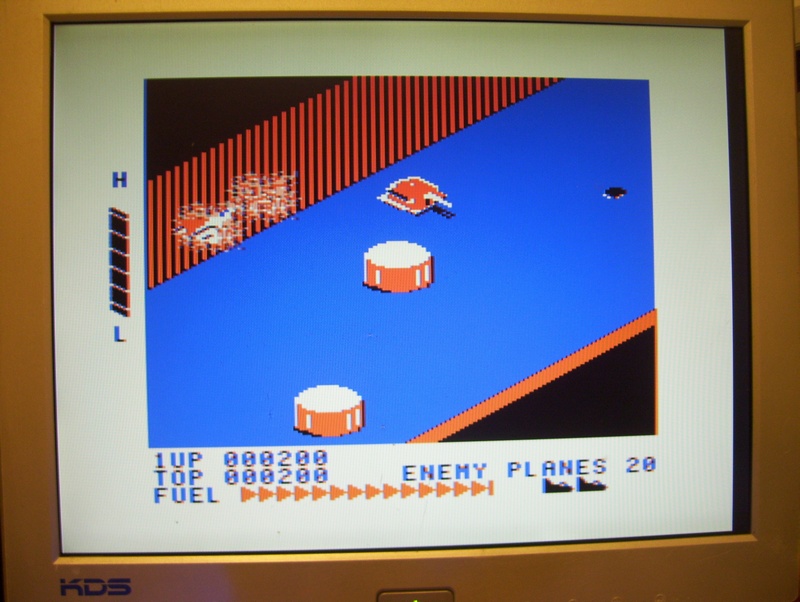
The picture on the right shows the SHRINK mode on which reduces the width of the video a little for whatever purpose you think it needs to be done. Notice how the full width mode spans completely across the monitor. This mode produces the best looking text. Note that if this mode is too wide for your tastes that you can always adjust the width on your monitor slightly to pull the image in a few pixels on either side. Likewise, you can probably expand the SHRINK mode a little using your monitor. It’s all about the sweet spot with this thing, and I’m still looking for it. |
|
||
>>> How to build an RGB2VGA converter for your CoCo 3. <<<
Perfect VGA has come to the CoCo 3. You might ask – “yea, right, what’s the catch?” There is no catch. This converter will knock your socks off when you see the most crisp colorful video ever for the first time coming from a CoCo 3.
You can either assemble this converter yourself or see if someone from the TRS-80 Color Computer facebook group is still assembling them, but please get one! You won’t regret it!
Article by Roger Taylor