|

|
There have been rumours of a secret 256 color mode hidden within the GIME chip architecture of the Tandy Color Computer 3.
This page reveals all the information that I have collected with the hope that one day the truth will be revealed.
|

Introducing the GIME chip
The GIME chip within the Color Computer 3 is an incredible piece of work. Not only does it almost completely emulate the functions of the 6847 VDG and 6883 SAM chip architecture of the earlier Color Computers but it adds a lot more! Advanced bank switching of RAM up to 512K, advanced interrupt handling and many more sophisticated graphics modes.
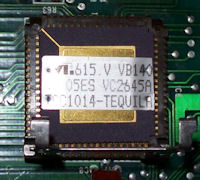
Prototype GIME
|
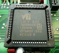
’86 GIME
|
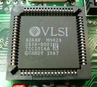
’87 GIME
|
The Color Computer 3 with its GIME chip has expanded upon the earlier models with their more limited 128×192 four color and 256×192 two color modes. The GIME chip has added new modes of 16 colors with a resolution up to 320×225 and 2 color modes with a resolution up to 640×225, the colors being selectable from a total palette of 64.
An interesting observation!
In 1999, I pointed John Kowalski’s attention to the block diagram of the GIME chip on page 96 of the Tandy Color Computer 3 service manual. John made an interesting observation that got us both curious. The diagram shows that the output of the “Reconfigurable (Graphics) Shift Register” is fed through a gate, followed by a “Register” and then on to the “Palette 16×6 Bipolar RAM”, finally ending up at another register then on to the DAC for output. This seems sound and as one would expect. What got John suspicious was that the output of the “Reconfigurable (Graphics) Shift Register” ALSO routed to another unlabeled “Register” which appeared to bypass the “Palette 16×6 Bipolar RAM” and fed into the register that follows it. John became suspicious that this register allowed 8 bit data from the shift register directly past the 64 color palette RAM !!
“Have you found the 256 color mode?”
We both puzzled over this but no one had any ideas of what it could be when I came into contact with a very prominant ex-radio shack employee via one of the CoCo IRC chat sessions. This person had a VERY close association with the development of the Color Computer 3. To say that his question to me, “Have you found the 256 color mode?”, raised the hairs on my back was a gross understatement !!
Here is an edited transcript of what he had to say about this mode…
|
Have you found the 256 color mode?
There is a real 256 color mode in there. I was hoping someone would discover it. It’s a real byte level pixel, 320×200 mode. It uses a yyyyyrgb format, 5 bits of intensity, 3 bits of color.
The mode is rather complicted to get to and did not work reliably on the first run of GIME chips and its been too long, I don’t remember the sequence anymore and I got overruled by Roach on the disclosure of the mode because it was too much competition with the 1000. It’s really the last secret in the Color Computer 3.
You can only have one 256 color page but it was very complicated to set up. It could view 512K and that was one of the problems because of the page at the top of memory. I was not allowed to tell anyone exactly what to look for either.
The only thing I remember about how to get into it is that you have to switch the mode while you are in the IRQ in the protected page at $FE00. It had to be set as a mode on the IRQ, it didn’t use the IRQ. While in that routine from an IRQ there is a machine state that changes the meaning of the graphics mode. I don’t have a clue what that pattern is anymore.
John Prickett ran out of pins to make it work so it reused some of them in while in the IRQ state.
|
We were able to get in touch with this person for a second time to get a few more questions in and here is the edited transcript …
| [MR X] It is a machine state, so it does require the right set of events and I am probably the only one who ever turned it on and played with it. My demo program put up changing color patterns. It was designed to be for games.
[JOHN] So, you’re saying that an IRQ routine that ‘itself’ is located in the $FEOO-$FEFF page is used to switch on the mode?
[MR X] That’s correct, John and as I remember it’s the only place you can do it.
[JOHN] Any hints as to what generates the IRQ signal? Does it matter?
[MR X] I did it on the timer I think.
[NICK] Is the 256 mode visible in both RGB and composite video output?
[MR X] I believe so, its a real mode.
[JOHN] So if I set up a TIMER based IRQ that jumps to the $FExx range… If I systematically trash random hardware registers $FFOO to $FFFF, eventually the mode should turn on.. shouldn’t it?
[MR X] It sees to me some of the regs had to be written with a given interval so random data is not going to do it and I can tell you the routine is not in Tandy archives anymore either.
[JOHN] What would be the reason for the program code to be in $FExx range? It’s not like the GIME can tell where the CPU’s PC is.
[MR X] That’s not true John, there are times the GIME does know. AII the coco files were distroyed 2 years before I left Tandy. No, once in the mode the computer acts as it did before, but no way to exit the video mode without a reset because the MMU is part of the addressing so the MMU has to intercept the address.
[JOHN] So.. the GIME remembers the last address issued on the CPU bus, and if that address is not exactly ‘some number’, the mode will not activate?
[MR X] The special page is treated differently by the MMU and the memory map becomes unstable during the mode change so it has to be one in that page. System needs to be in the RAM mode.
[NICK] MMU on or off?
[MR X] On.
[NICK] CoCo1/2 compatible mode on or off?
[MR X] CoCo 3 mode.
|
GIME chip designer found!
My next avenue of pursuit was to locate the man responsible for the design of the GIME chip and I was given the name, John Prickett. My search on the internet located a John Prickett working for AMD at the time and here is his response to my question…
| I’m John Prickett, and I did design the chip you referenced, but that was 14 years and 50 designs ago. I couldn’t possibly tell you any of the internal intricacies of the chip now. You probably know more about it that I do right now.
I do seem to remember that it was 64 colors only , we only used a 6-bit palette, and so I very much doubt that there is a ‘hidden 256 color’ mode. But I could be wrong.
Sorry I couldn’t be more help, John
|
More Proof!
During my job as PennFest 2000 co-organiser, I came into contact with Mark Hawkins of Microware. Mark is one of the 3 people who developed the CoCo3’s Super Extended Basic and is one of the “Three Mugsters” that appears on the CTRL-ALT-RESET page. I asked Mark about this mode and he was unfamiliar with it but he said that he would look through the archives at Microware for old documentation about the GIME chip. He found the original “Color Computer Custom Video Proposed Feature List” document which came from Tandy’s R&D section. All of the info is as found in the service manual except for the cover page which lists the 256 color mode!
This proves that the mode was at least in the planning stages. What we are unsure of from this page is what the references are about 1 and 2 banks of RAM and how that effects the modes. We have seen references to this in CoCo3 memory maps but it has always been ignored.
FF91:
|
INITIALIZATION REGISTER 1
|
|
|
Bit 7 – Bit 6 –
Bit 5 –
Bit 4 –
Bit 3 –
Bit 2 –
Bit 1 –
Bit 0 – |
0 = Two banks of DRAM 0 = 64K chips, 1 = 256K chips
Timer Input Clock Select 1=70ns, 0=63ns
NOT USED
NOT USED
NOT USED
NOT USED
MMU Task Register Select |
With closer scrutiny of this R&D document, we find only one additional piece of information that is not to be found in the normal CoCo3 memory maps. On page 7 of this document that covers the CoCo1/2 compatible registers of $FF20 to $FF23, we find handwritten at the bottom of the page the following…
| FF27 |
Will also be used for power-up system configurations. Bit definitions are TBD.
|
Could this be one of the mystery registers or was it an abandoned idea?
Infinite Scanlines Mode
Another interesting observation that has me curious (but may not be related to the 256 mode) is the function of BITS 6 and 7 in the FF99 Video Resolution Register. The functions are listed in the CoCo3 memory maps as…
|
Lines per Field
|
|
BIT 1
0
0
1
1
|
BIT 0
0
1
0
1
|
192
200
210
225 |
The Lines Per Field is the number of vertical scanlines or vertical resolution of the mode. All of these work fine except for the 210 setting. This does not create 210 lines. Instead it appears to create an infinite number of lines. With this setting, the display stretches past the top and bottom and it seems to pick whatever color the GIME was processing at the time the mode is set. If it was in the border region of the screen, it keeps generating this color otherwise it repeats the current color in the active portion of the screen.
Palette Bypass found?
Robert Gault has made an interesting observation. Whether it is a clue to the 256 mode or just another bug in the GIME, we don’t know. Here is his text…
The Unravelled series of books indicates that the $FF99 bits have the following meanings…
|
Bits 3-4 HRES
|
Bits 0-1 CRES
|
| 111 = 160 bytes/row 110 = 128
101 = 80
100 = 64
011 = 40
010 = 32
001 = 20
000 = 16 |
11 = undefined 10 = 16 colors
01 = 4
00 = 2 |
The above data applies when $FF90 is set for Coco3 (%0xxxxxxx). What I have found is that when $FF90 is set for Coco1&2 (%1xxxxxxx), the above table for HRES has different meanings. . In PMODE graphics the table should not apply and it should not matter what value is sent to $FF99.
When in Coco 1&2 mode ($FF90=%1xxxxxxx) palettes $FFBA-$FFBB determine the PMODE4 screen colors. $FF9A determines the border color for all Coco modes.
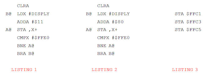
As PMODE4 is two color, each bit of a screen address determines the palette for that pixel. The original testing was made with $FFBA = $3F and $FFBB = 0. The screen data in my test was controlled by the code loop. SEE LISTING 1
This loop was expected to change the screen rapidly with a variety of vertical stripes. In Composite mode this would yield artifact color and in RGB mode white and black stripes. However, what happened was a very slow flip between an all white or all black screen. I thought the palettes had been bypassed which at first glance seemed reasonable.
Further testing where $33 (RGB yellow-green) was one of the colors proved that the palettes were still active even though there were no vertical stripes.
The effect of HRES=1xx clearly corrupts (’86 GIME) how the video system responds to the screen data. How could one explain the lack of the vertical stripes for the above code? Eventually I realized that the extended delay in flipping between colors was a clue. Strange as it might be, perhaps only two values of the 256 possible for each screen byte functioned!
What actually happens is that all screen bits are ignored except for %1xxxxxxx. This can be proved if the above routine is changed to… SEE LISTING 2
The screen rapidly changes between the two chosen colors.
The above effect of $FF99 can be negated with the video behaving normally as a PMODE4 screen if the SAM bytes at $FFC0-$FFC5 are set for DMA mode: SEE LISTING 3
The Motorola R.M.S. Chipset. Precursor to the GIME?
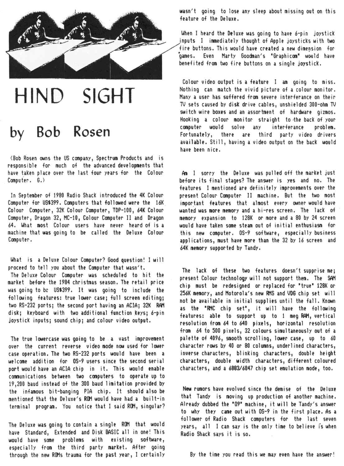
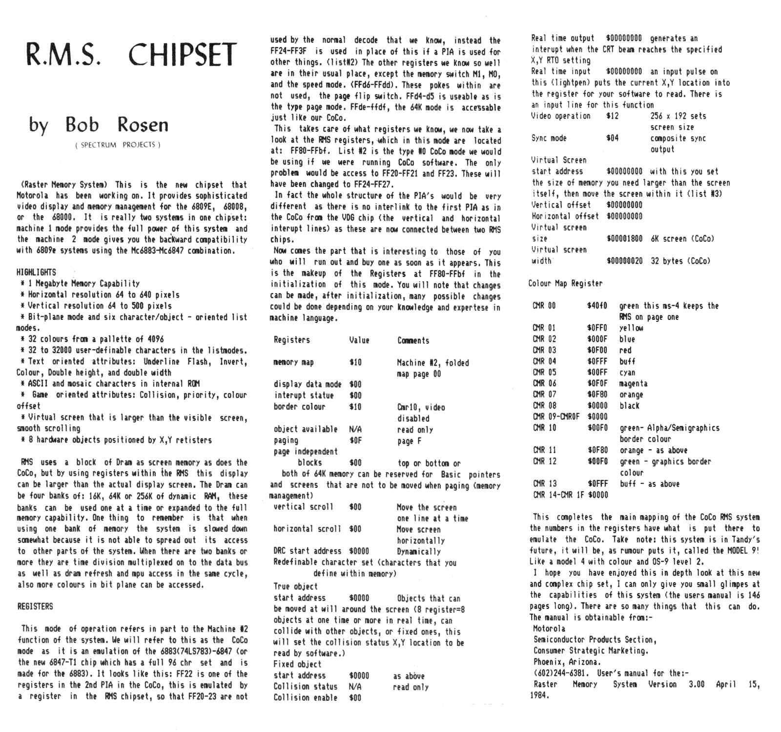
The August 1985 issue of the Australian Rainbow magazine had two interesting articles from Bob Rosen, founder of Spectrum Projects. The first article titled, “Hind Sight”, talks about the Deluxe Color Computer. This was to be the replacement for the CoCo 1/2. This design was scrapped and a more advanced design was commisioned, possibly to be based on the new chipset from Motorola called the R.M.S. (Raster Memory System) chipset. A second article in the same issue also by Bob Rosen called “R.M.S. Chipset” explains the features and some of the design aspects of this chipset.
Of course, we know now that that chipset never eventuated in any production systems but the design must have been at least close to completion because Motorola had a user manual available. Bob mentions that Motorola were designing this chipset to have 2 modes of operation. Mode 1 provided all new powerful features while Mode 2 was an emulation of the SAM and VDG setup in their older design as used in the CoCo 1/2. It’s interesting to note that the GIME chip does exactly the same thing.
I find it hard to believe that Motorola would be designing such a chip with backward compatibility to it’s old SAM/VDG design for anything other that the next Tandy Color Computer. What other commercial computer used the SAM/VDG combination apart from the CoCo, all the CoCo clones and a machine called the VZ-200/300 here in Australia?
I believe it was destined for the CoCo3 but what happened? The specifications of the GIME and the RMS chipset are very similar, except that the RMS chipset included support for 1Mb of memory and hardware sprites. Was it redesigned into the GIME by another company? Is it the same chipset with features removed?
As I said, these articles appeared in the Australian Rainbow magazine in August 1985, almost a year before the CoCo3 was released.
I have scanned each article into jpeg images and they can be downloaded here.
HIND SIGHT R.M.S. CHIPSET
Current Status
John and I have run tests on the various GIME chip locations, running random data and experimenting with all the areas of the map that are marked as undefined or not used. The mode, if it truly exists, does not take the form of a normal register function. As our friend on the IRC chat explained, the designers ran out of pins to make it work properly and had to re-use pins during a specific machine state of the GIME. This makes it extremely difficult to locate because even if we are looking at the right places to setup the mode, the mode is non-functional and therefore will not present itself unless this specific state is met.
We need more information and vital clues in order to proceed further. What are those 2 registers that appear to be part of some bypass of 8 bit video data in the GIME chip and how are they accessed? Could the mode have been removed from final production GIME chips or does the mode still exist but has been carefully “hidden” under the request of Tandy management so as not to conflict with the sales of the Tandy 1000 line of PC compatibles in the product line at the time?
UPDATE (April 2013)
The CoCo3 prototype board has been located and is currently owned by Allen Huffman. He has taken many high resolution images of the board and made them available on the web for people to examine.
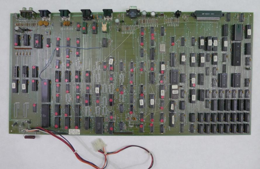
Several people have analysed the pictures. James (jdagget) has done a lot of work and has made an important discovery regarding a mystery chip.
“Down on the corner of the board near where the composite video and audio RCA jacks are is a TBP28S42 4096 bit PROM. This chip is configured as a 512 byte ROM!!!! A chip like that could be used as a lookup table.
Now compare that comment with this text from the Tandy R&D document
“Palette RAM provides 64 possible (16 displayed) or 512 possible (256 displayed) colors, depending on mode.”
This prototype could be using that PROM as the 512 color lookup table.
What if this PROM was removed and reduced to just 64 bytes as a cost reduction? RAM/ROM was expensive back in 1985 and this seems quite likely. Would that mean that the circuitry to display these colors is still there in the current GIME chip but has nowhere to obtain the data?
Could this secret mode be a matter of feeding these circuits the missing data via an interrupt driven routine in software? Could this be the bypass register that Sock Master found? A possible redirection register?
The question remains, is the production GIME’s video DAC’s actually capable of delivering 3 bits per RGB (3 bits=8 – 8x8x8=512) instead of the current 2 (2 bits=4 – 4x4x4=64)?
If the mode is not available in RGB, maybe it’s only available in Composite (NTSC CoCo’s)?
UPDATE (January 2014)
In Boisy Pitre and Bill Loguidice’s book, CoCo – The Colorful History of Tandy’s Underdog Computer, there is an interview with John Pricket, the GIME chip designer. Unfortunately, John does not confirm or recall any existance of a 256 color mode. According to Boisy, John was asked about this mode and shown information from this web page but had no recollection of any such mode being in the planning.
Strange considering it is listed as being part of the planned design of the GIME chip in the official Tandy R&D document.
And what of the 512 byte PROM on the prototype motherboard?
In the book, it mentions that the first production of the GIME (1986) had an anomoly with the behaviour of the keyboard interrupt. John was hired to correct this anomoly and a new production of the GIME (1987) was done.
Strange the glaring fault of the 210 scanlines mode wasn’t corrected. This fault disabled the scanline counter on both versions of the GIME. A correction to the horizontal scrolling was also done in the 1987 GIME and changes to video timings but there is no mention of these also.
Mark Seigel (Mr X), the lead CoCo3 project manager at Tandy has said it did exist at some point but cannot recall the actual details apart from what has been documented on this web page.
I still feel the story of this 256 color mode has yet to be unveiled. I don’t believe it exists in production GIME’s but I do believe it existed somewhere, even if it was at least only in the idea stages.
|


